How high-voltage indicators work
The device utilizes the principle of electric field coupling between the high-voltage electric field and the sensor, and performs inductive (non-contact) measurement outside the safety distance, and the working principle block diagram is as shown in the figure below:
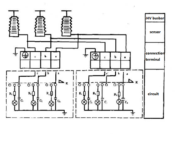
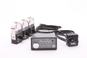
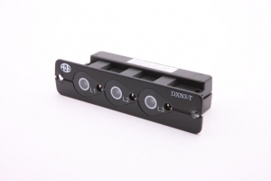
The high-voltage live line indication device consists of two parts: a sensor and a display. The sensor has three branches, which are respectively aligned with the "A, B, C" three-phase charged body, and has no direct contact with the high-voltage charged body, and maintains a certain safe distance. It accepts the electric field signal of the high voltage charged body and transmits it to the display for comparison and judgment:
When the device under test or the network is powered, the “A, B, C” three-phase indicator lights up, the “Operation” indicator is off, and the forced blocking signal is output (to realize the functions of interlocking indication and interlocking signals output to the electromagnetic lock for auto lockout) ;
When the device under test or the network is not powered, the “A, B, C” three-phase indicator lights are off, the “Operation” indicator is on, and the blocking signal is released, and the device operation can be performed;
The device uses split phase control, when any phase is charged. That is, the flash alarm and output a forced blocking signal. When the indicator loses control power, the indicator outputs a forced blocking signal to maintain the locked state;
The indicator has a “self-test” function, which can automatically detect various function modules of the sensor and display. When any malfunction occurs in the device, the “power” indicator will flash, the “operation” indicator will not light, and the output will always be forced. The latching signal remains latched.